The fragmented electronics ecosystem is the real AI bottleneck
A design's truth is scattered across five ECAD formats, a PLM system, a folder of PDFs, distributor portals, and an MCAD tool — none of which share a language. AI needs the whole picture. The industry has spent forty years making sure no single tool has it.
 James Pentalow · VP of Revenue, Circuitly
6 min read
James Pentalow · VP of Revenue, Circuitly
6 min read
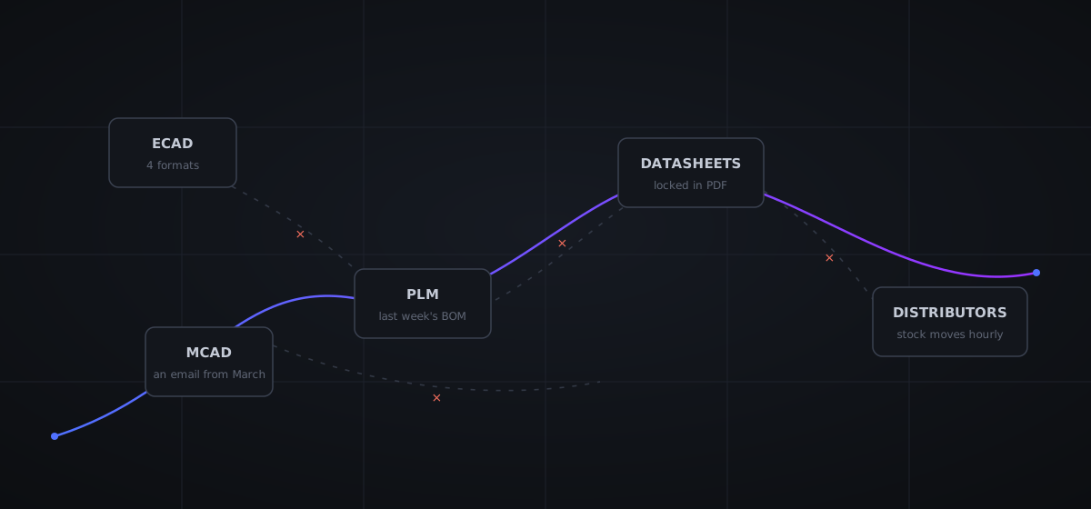
Pick any mid-size electronics company and trace where the truth about one product actually lives. The schematic is in Altium. The requirements are in a Word document, or if you're lucky, a PLM system like Duro or Arena. The BOM exists in three versions: the one in the ECAD tool, the one in the PLM, and the one in procurement's spreadsheet — currently disagreeing about two line items. Component datasheets are PDFs in a shared drive, some of them superseded revisions. Stock and pricing live in DigiKey and Mouser portals, checked by hand. The enclosure lives in SolidWorks or Onshape, and the only link between the board outline and that enclosure is an email from March.
Nobody designed this. Everybody has it.
And when teams ask why their AI initiatives underdeliver — why the model that aces benchmark questions can't answer "can we still build this product next quarter?" — this scattering is almost always the real answer. Not the model. The plumbing.
Electronics data is fragmented across ECAD silos, PLM islands, PDF datasheets, distributor portals, and MCAD walls — five worlds with no shared language. Human engineers bridge the gaps invisibly, from memory. AI agents can't: they know only what their integrations reach. Fragmentation is therefore not an inconvenience for AI in electronics; it is the bottleneck.
The five silos, briefly
ECAD. The design tools themselves don't speak to each other. KiCad, Altium, Cadence Allegro, and Siemens Xpedition each use their own formats, their own library conventions, their own constraint systems. Moving a design between them is a migration project, not an export. This is not an accident of history — proprietary formats are the lock-in strategy, and it has worked for decades. The consequence: any tool that wants to work across the industry has to speak four-plus native dialects, which is why almost none do.
PLM. Product lifecycle systems hold the released truth — approved BOMs, revisions, change orders. But they grew up on the manufacturing side of the wall, so in most companies the PLM learns about a design change days or weeks after the ECAD file changed, via a manual export ritual. The gap between "what engineering is designing" and "what PLM says exists" is where phantom BOM lines breed.
Datasheets. The most important technical documentation in the industry ships as PDF — a format designed to describe printed pages, not data. The absolute-maximum table, the recommended land pattern, the footnote that says the part needs 10 µF of output capacitance per ampere: all of it is locked in layout-dependent typography that extraction tools mangle. Multiply by the fact that a single part may have six datasheet revisions and the one in your shared drive is from 2021.
Distributors. Stock, pricing, and lifecycle reality live with DigiKey, Mouser, and a hundred other distributors and franchises. This data changes hourly and arrives through portals built for humans with browsers, plus APIs of wildly varying quality. Most teams "integrate" by having an engineer check availability at design time and a buyer discover the truth at order time.
MCAD. The enclosure, the keep-outs, the connector that must land exactly 3.2 mm from the wall — mechanical truth lives in a different tool, owned by a different engineer, synchronized by exported STEP files and goodwill. Every hardware team has a story about a board that met every electrical requirement and didn't fit in the box.
Why exchange formats didn't fix it
The industry has tried standards, and it's worth being precise about why they fell short, because the failure is instructive. EDIF, the 1980s attempt at a universal netlist interchange, fragmented into vendor dialects until "EDIF-compatible" meant almost nothing. ODB++ and IPC-2581 succeeded — genuinely — but at a narrow job: describing finished manufacturing output, the dead snapshot handed to a fab. STEP does the same for mechanical geometry.
What none of them carry is the living design: the schematic's intent, the constraint system, the reason this net is matched-length, the link between requirement REQ-PWR-0042 and the shunt resistor that satisfies it. Exchange formats move artifacts between silos. They were never designed to create a shared, current, queryable source of truth — which is the thing collaboration needed all along, and the thing AI cannot function without.
A snapshot format tells you what the board is. It cannot tell you why — and "why" is where all the engineering lives.
The system runs on human glue
Here's the part that hides the problem: fragmented electronics development mostly works, because human engineers are spectacular integration middleware. The senior EE holds the requirements in her head while she draws the schematic. She remembers that this customer's product needs automotive-grade parts, alt-tabs to DigiKey to sanity-check stock, recalls the enclosure constraint from a design review, and mentally flags that the regulator she's reusing had an errata on the last project.
None of that context lives in any system. It lives in her. And that has three costs that compound quietly: it doesn't scale (she is one person), it doesn't transfer (when she leaves, the glue goes with her), and it doesn't audit (six months later, nobody can reconstruct why the 1% resistor became 0.1%). The industry calls this "experience." It is also, structurally, a single point of failure with a notice period.
AI can't alt-tab
Now put an AI agent into that environment and the hidden costs become visible instantly. The agent asked to review a power supply sees exactly what its integrations expose — say, the schematic. It does not see the requirement doc that specifies 10 mA resolution, the PLM record showing the preferred-parts list, the datasheet revision with the new thermal figure, the distributor feed showing the part it's evaluating went to 26-week lead time, or the enclosure model with the 11 mm height limit directly over the inductor it's about to approve.
A human reviewer's answer, informed by all five, is engineering. The agent's answer, informed by one, is a plausible-sounding fraction of engineering — and this is where most "AI didn't work for us" stories actually come from. The model reasoned correctly over the context it had. The context was one-fifth of the truth. (This is the infrastructure argument at the core of why AI hasn't worked for electronics: model intelligence was never the binding constraint.)
What a digital thread actually requires
The name for the alternative is the digital thread: one connected, traceable line from requirement to schematic to component to BOM line to purchase to mechanical fit to manufacturing file. Not a single monolithic tool — that ship sailed, and the vendors made sure of it — but a connective layer over the tools you already run. Concretely, that layer has to do four unglamorous things:
- Speak native formats. Read and write KiCad, Altium, Cadence, and Siemens files as they are, because no one is migrating four product lines to a new tool for the sake of an integration.
- Treat external systems as live sources of truth. PLM records, distributor stock, datasheet revisions, MCAD geometry — pulled by API at decision time, never cached in someone's memory or a stale export.
- Preserve linkage. Keep the requirement-to-component-to-BOM-line trace as data, so "why does this part exist?" and "what does this requirement change touch?" are queries, not archaeology.
- Version everything. The thread is only trustworthy if every change to it is recorded, diffable, and reviewable — which is why Git-style version control sits underneath, not beside, the whole thing.
Notice that this list is also, almost verbatim, the list of what an AI agent needs to do real design work. That's not a coincidence — it's the whole point. The digital thread and the AI harness are the same infrastructure viewed from two angles: one solves the fragmentation that's been taxing human engineers for decades, the other feeds the agents that fragmentation was starving. (We've written about the harness side in why you need a harness, not a chatbot.)
The electronics industry doesn't have an AI problem. It has a forty-year-old data fragmentation problem that AI finally makes impossible to ignore — and, for the first time, expensive enough to fix.
Frequently asked questions
Why is electronics design data so fragmented?
Forty years of commercial incentives. Each ECAD vendor built proprietary formats that lock teams into their toolchain; PLM systems grew up separately around manufacturing; distributors built portals rather than open data feeds; and component documentation standardized on PDF — a print format — because it was universal. Every silo made local sense. The global result is that no single system holds the whole truth about a design.
Didn't standard formats like EDIF, IPC-2581, and ODB++ solve interoperability?
Only for narrow slices. ODB++ and IPC-2581 describe manufacturing output — the finished board handed to a fab — not the living design with its schematics, constraints, and intent. EDIF died of vendor-specific dialects. Standard exchange formats move snapshots between tools; they don't create a shared, editable source of truth, which is what both collaboration and AI actually need.
Why does fragmentation hurt AI more than it hurts human engineers?
Humans paper over the gaps without noticing — an engineer holds the requirement in their head, alt-tabs to the distributor portal, remembers the enclosure constraint from a hallway conversation. An AI agent has none of that ambient context: it knows exactly what its integrations give it access to, and nothing else. Fragmentation that costs a human minutes of alt-tabbing costs an AI the context it needed to be right.
What is a digital thread in electronics?
A digital thread is a connected, traceable line through every stage of a product's data: requirement → schematic → component choice → BOM line → purchase → mechanical fit → manufacturing file. In a threaded workflow, a requirement change propagates visibly to everything downstream of it, and any BOM line can be traced back to why it exists. It's the opposite of the status quo, where those links live in engineers' memories and out-of-date spreadsheets.
James Pentalow
James is a two-time founder and GTM lead at Circuitly. He's spent almost a decade working with customers in the electronics space and has been building agentic systems since 2022.
One thread through all of it.
See how Circuitly agents pull requirements, parts, datasheets, stock, and mechanical constraints into a single loop — on your own design data.
Book a Call